
The principal factors governing the pipe size to be used are the nature of the fluid, the flow velocity and pressure drop. The sizing criteria are different depending on whether the pipe is carrying a single-phase liquid, a single-phase gas or a two-phase mixture of liquid and gas.
What are the sizing criteria for a pipe carrying a single-phase liquid?
Pipes carrying single-phase liquids are sized primarily on the basis of flow velocity. There are recognised limits for the maximum and minimum flow velocities in a pipe (e.g. API RP 14E). For example, for a pipe transporting liquid in single-phase from one pressure vessel to another by differential pressure, the flow velocity should not exceed approximately 4.6 metres per second and, if possible, should not be less than approximately 0.9 metres per second. At these flow velocities, the overall pressure drop in the pipe will usually be small.
How does the designer calculate the flow velocity?
There are equations available that calculate the flow velocity based on the flow rate and inside diameter of the pipe. The flow velocity, V, is directly proportional to the flow rate, Q, and inversely proportional to the cross-sectional area of the pipe bore, A, where A = ¼ ∙ π ∙ D²; D being the inside diameter of the pipe, i.e.

The flow rate, which is the amount of liquid that needs to be moved through the pipe in a given time, is effectively fixed, but the pipe bore, D, can be varied to achieve the desired flow velocity.
So how does the designer know what inside diameter to use?
The designer will generally try to use the smallest inside diameter he/she can in order to minimise the pipe size. If the calculated flow velocity is in excess of the recognised maximum, the designer will have to use a larger pipe size. For process pipework, the designer will try to use a standard pipe size (e.g. ASME B36.10) and schedule as this should be the most cost effective approach. In the case of pipelines, sometimes it may be cost effective for the designer to use a non-standard pipe size based on the required inside diameter and wall thickness; where this is the case the pipe usually has to be manufactured to order.
When is the pressure drop important in a pipe carrying a single-phase liquid?
It is important in pump suction piping, where it is critical that the pressure stays above the vapour pressure (VP) of the liquid; if not, in a process known as cavitation, the reduction in pressure below the VP could cause bubbles to form in the fluid. As the pressure increases above the VP within the pump the vapour bubbles can implode, generating intense shockwaves. These shockwaves can cause severe erosion, which in turn leads to pitting that can dramatically shorten the life of the pump.
How does the designer calculate the pressure drop?
There are various equations available to calculate the pressure drop, ΔP, based on the flow rate, the density and viscosity of the liquid, the flow velocity and the inside diameter of the pipe. For a straight pipe, the pressure drop is given by the equation.
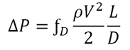
Where ƒD is the Moody friction factor, ρ is the density of the fluid, V is the average velocity of the fluid in the pipe, L is the length of pipe and D is the inside diameter. The Moody friction factor can be read from a Moody diagram, which shows the friction factor, ƒD, plotted against the Reynolds number, Re, for various relative roughness values, ε / D.
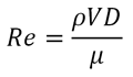
Where, μ is the liquid viscosity.
Given that V = 4Q /πD ², it can be seen that the pressure drop is proportional to the square of the flow rate, Q, and inversely proportional to the inside diameter of the pipe to the power five, i.e.

Put simply, the pipe bore has an enormous effect on the pressure drop for a given flow rate; especially in small bore pipework. So even if the flow velocity is acceptable, it may still be necessary to increase the pipe size to avoid an unacceptable pressure drop.
What are the sizing criteria for a pipe carrying a single-phase gas?
In essence, pipes carrying a single-phase gas need only be sized so that the outlet pressure at the end of the pipe is high enough to satisfy the next piece of equipment. The flow velocity is only a problem if it causes ‘noise’ or if corrosion inhibitor is going to be used.
Why is ‘noise’ a problem?
One obvious reason is that it does not make for a very pleasant working environment. However, more importantly, ‘noise’ can produce acoustic vibration, which if severe may result in fatigue failures. Problems with ‘noise’ can generally be avoided if the flow velocity is kept below approximately 18 metres per second. Whilst higher velocities are possible, these should only be used if pipe routing, valve choice and/or placement are selected to minimise or isolate the ‘noise’.
How does the gas velocity affect the use of corrosion inhibitor?
If corrosion inhibitor is going to be used the velocity of the gas may need to be reduced to avoid stripping the inhibitor film from the pipe wall. In this case, calculating the limiting velocity is not straightforward and it may be necessary to carry out laboratory trials to establish it.
So is the calculation for the gas velocity the same as the calculation for the flow velocity for a single-phase liquid?
It is similar but not identical; the compressibility of the gas, the operating temperature and pressure also have an influence. The main thing is that the gas velocity is again directly proportional to the flow rate and inversely proportional to the cross-sectional area of the pipe bore. So for a given flow rate, if the temperature and pressure are fixed, the only way the designer can reduce the gas velocity is to increase the pipe bore.
Is the pressure drop important in a pipe carrying a single-phase gas?
Yes, but only in as much as it affects the outlet pressure.
How does the designer calculate the pressure drop?
Again, there are equations available, which are very similar to those used to calculate the pressure drop in a pipe carrying a single-phase liquid in that the pressure drop is proportional to the square of the flow rate and inversely proportional to the square of the cross-sectional area of the pipe bore. So, as in the case of a single-phase liquid, the inside diameter has an enormous effect on the pressure drop.
Are the sizing criteria for a two-phase gas/liquid system the same as those for single-phase gas and liquid systems?
No. In a two-phase gas/liquid system erosional velocity is a major concern. Experience has shown that above a certain velocity a loss of wall thickness occurs by a process of erosion corrosion, which can greatly reduce the design life of the system. See the introduction to corrosion article for more information.
How does the designer know the velocity above which erosion may occur?
There is an empirical equation available for determining the velocity above which erosion may occur. This is based on the density of the gas/liquid mixture at flowing pressure and temperature and a constant that is dependent on whether fluid is solids-free and/or whether corrosion is also likely to occur.
So how does the designer size the pipe based on the erosional velocity?
There is an equation available that allows the designer to calculate the minimum cross-sectional area required to avoid fluid erosion. The minimum inside diameter can be calculated directly from the minimum cross-sectional area.
Is the pressure drop important in a pipe carrying two-phase gas/liquid?
Yes. In two-phase systems, if possible the minimum velocity needs to be kept above approximately 3 metres per second to avoid slugging (i.e. the liquid and gas phases separate). This is particularly important in long lines with elevation changes.