In my earlier articles on the fundamentals of carbon steel I discussed the effect of time on the transformation process and the microstructures that result from the decomposition of austenite depending on the cooling rate. I introduced the concept of the time-temperature-transformation (TTT) diagram (figure 1) and explained how it enables the metallurgist to predict how a steel will respond to a particular heat treatment. I do not intend to go into too much detail about TTT-diagrams in this article (that will be the subject of a later blog); I have included figure 1 simply to help explain how different products, resulting from the decomposition of austenite, form.
Depending on the cooling rate, the decomposition of austenite occurs according to three separate, but sometimes overlapping, mechanisms and results in three different reaction products; namely, pearlite, bainite and martensite.

A) Pearlite
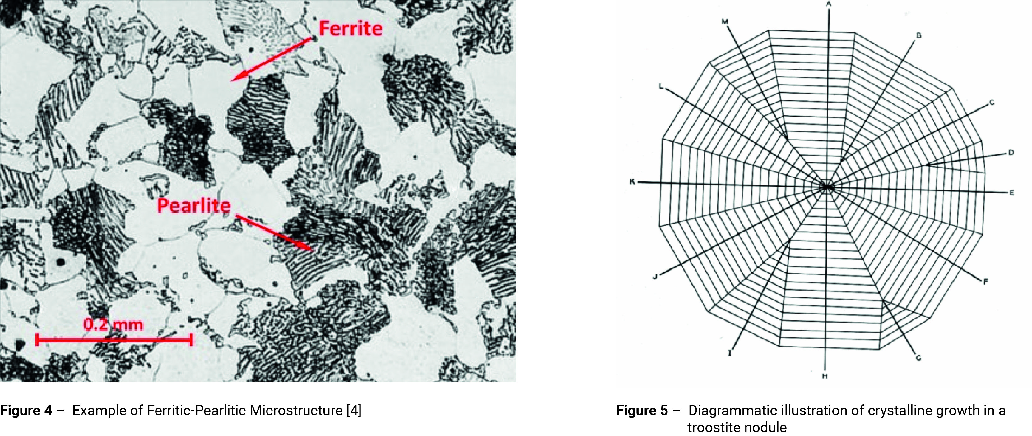
The upper dotted curve in figure 1 represents the beginning of the formation of ferrite. The broken curve just below it indicates the beginnings of the transformation of the remaining austenite into a ferrite-cementite (carbide) aggregate. In the upper portion of the pearlitic range in figure 1, the transformation process resembles the solidification of crystals from a liquid by the formation and growth of nuclei of carbide followed by the formation of ferrite by side nucleation with side and edge growth, as indicated in figures 2 and 3. An example of a ferritic-pearlitic microstructure is shown in figure 4.
If the steel is cooled slowly to around 700°C the formation of nuclei is slow, but growth then proceeds rapidly to form large pearlite colonies; in some cases covering several austenite grains.

If the temperature is lowered to around 500°C before transformation takes place, the nucleation period decreases and the pearlite becomes increasingly fine. Large numbers of nuclei form at the austenite grain boundaries and around voids or inclusions within the structure. Growth is slower than at higher temperatures and this produces fan-shaped radial grains sometimes referred to as nodular troostite, figures 2 and 5 [2, 3]. Nodular troostite is an aggregate of ferrite and cementite. Like pearlite it has a lamellar structure, but the platelets are much more closely spaced. The condition of the ferrite and cementite in relation to one and other is not stable and they tend to stratify forming pearlite. Hence, the microstructure is likely to take on the appearance of fine pearlite.

B) Bainite
If the temperature is reduced to between about 500° and 350°C before transformation takes place, ferrite nuclei form; which are coherent with the austenite matrix. As these nuclei propagate, excess carbon partitions into the residual austenite; cementite then precipitates from the carbon-enriched austenite between the ferrite plates. The actual temperature at which this reaction begins is known as the bainite start temperature (Bs). A number of formulae are available for predicting the Bs temperature; some are based purely on the composition, others take into account the prior austenite grain size [5-9]. The formula shown below, which has been developed by Kang [6], takes into account both the composition and prior austenite grain size.
Bs = 634.8 - 193.1C + 102.4C2 - 31.2Mn - 4.6Si - 18.6Ni - 32.4Cr - 15.6Mo + 10.36ln(dγ )
Where, dγ is the prior austenite grain size in microns and the alloy content is in wt%. This formula is reliable for chemical compositions in the range: 0.10-1.00% C, 0.17-1.91% Mn, 0.40% Si max, 2.10% Ni max, 2.16% Cr max, 1.96% Mo max and prior austenite grain size in the range 6.7-1.62 microns.
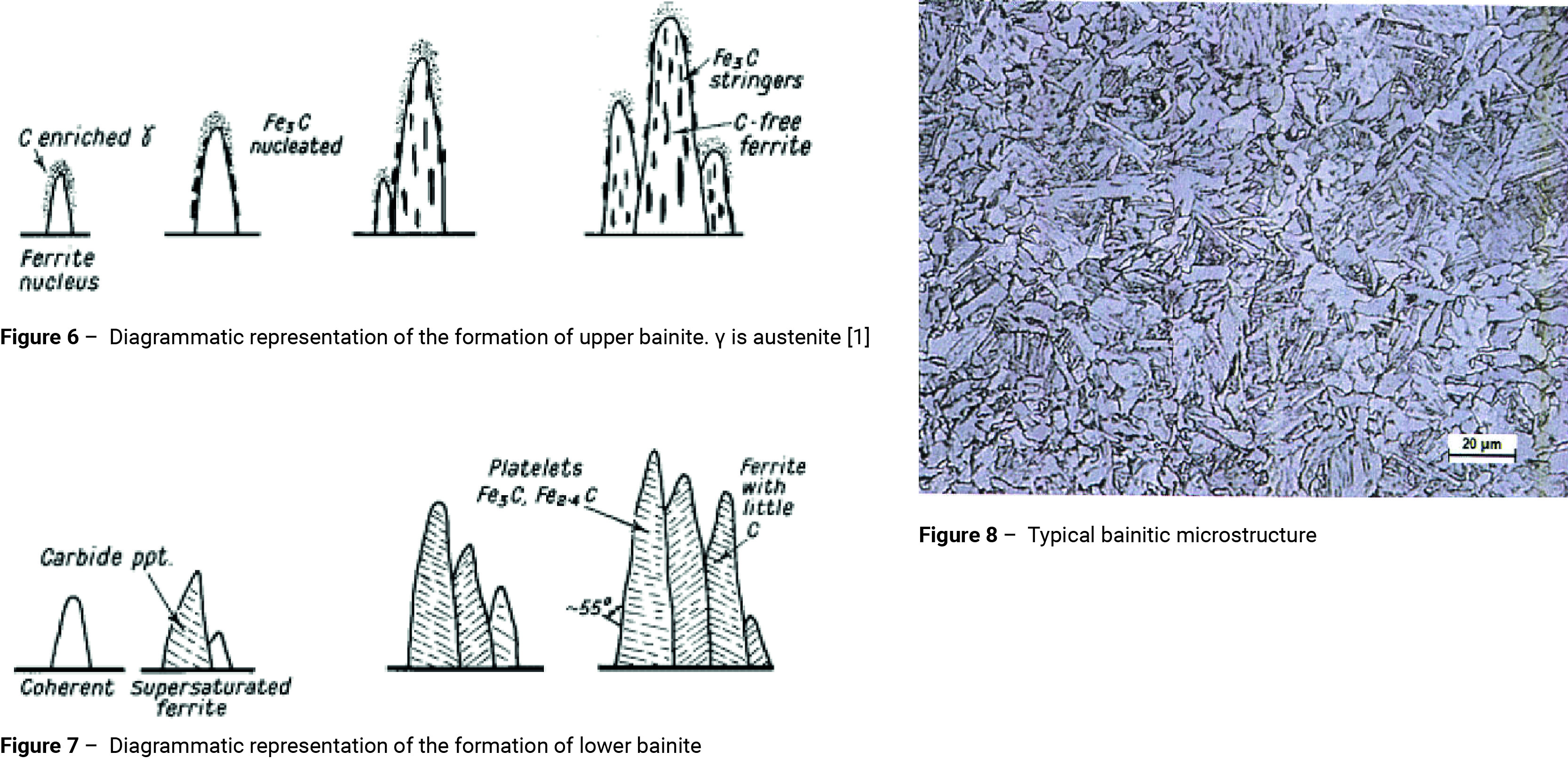
The propagation of the ferrite plates is accompanied by a change in the shape of the transformed region. The parent austenite cannot accommodate the deformation associated with this shape change elastically, and deforms plastically in the region adjacent to the bainite. This plastic deformation stifles further growth of the ferrite plates and the transformation proceeds with the formation of new plates [10] as shown in figure 6. The carbides tend to lie parallel to the long axis of the bainite needle to form the typical open feathery structure of upper bainite.
If the temperature is reduced to below 350°C before transformation takes place, then coherent ferrite supersaturated with carbon will form. However, because of the slower diffusion associated with the reduced transformation temperature some of the carbon precipitates inside the supersaturated ferrite. A fine dispersion of plate-like carbides forms [11], orientated transversely at an angle of 55° (figure 7). A proportion of the carbide is Fe2.4C and the ferrite contains a little dissolved carbon. This lower bainite structure is somewhat similar to lightly tempered martensite (figures 8 and 10).

There is no fundamental difference in the transformation mechanism for upper and lower bainite [12]. The bainitic ferrite grows supersaturated with carbon. The excess carbon may then partition into the residual austenite or precipitate in the ferrite in the form of carbides. If the latter process is dominant, lower bainite is obtained. Upper bainite is obtained only when carbon partitions relatively rapidly into the residual austenite, i.e. before the carbides have an opportunity to precipitate. According to this model, it is also possible to form a mixed microstructure of upper and lower bainite in a narrow temperature range around the lower bainite start temperature (LBs). This is because the carbon enrichment of the austenite caused by upper bainite transformation can result in a subsequent formation of lower bainite [12].
C) Martensite
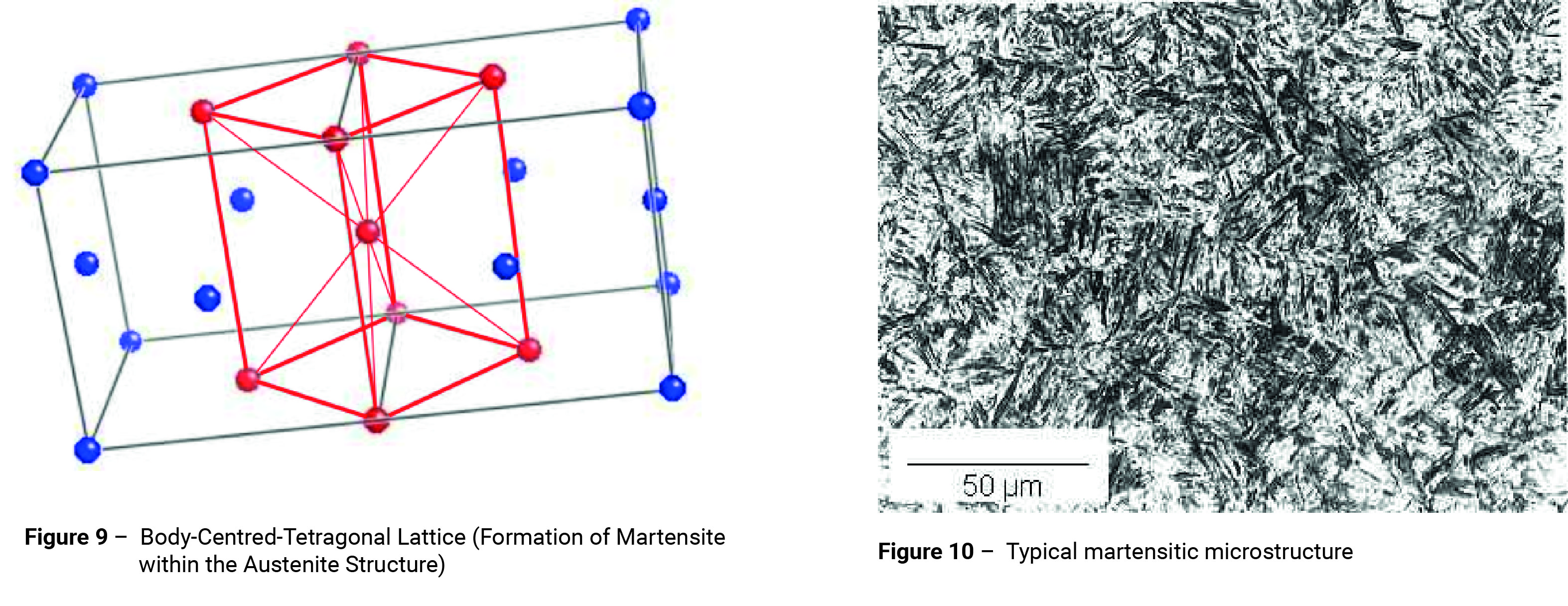
If quenching is rapid enough such that the temperature of the steel is reduced to below about 250°C before any nucleation can take place, the temperature will be too low for diffusion to occur. The carbon atoms will be trapped within the austenite matrix. Where this is the case, the austenite transforms incompletely into a distorted body-centred structure known as martensite (figure 9); the plates of which are formed virtually instantaneously suggesting that the mechanism of formation is not nucleation and growth, but a shearing process. This resembles the process of mechanical twinning and involves very little atomic movement, but considerable internal stress due to the shear and to the position of the carbon atoms. A typical martensitic microstructure is shown in figure 10.
As the temperature decreases, the elastic energy increases and eventually causes a shear in a part of the matrix. This stabilises the rest of the matrix such that further shear can only occur if the temperature is lowered and more energy gained. The amount of martensite formed is practically independent of time and depends primarily on the temperature at which the steel is held. Hence a proportion of austenite is usually retained in quenched steel which can be reduced in amount by a decrease in temperature. This fact is used in sub-zero quenching.

The temperature at which martensite begins to form (Ms) is progressively lowered as the alloy content of the steel is increased. Provided that all carbides have been dissolved in the austenite, the following empirical formula developed by Steven and Haynes [13] can be used for calculating the Ms temperature from the chemical composition.
Ms=561.1 - 473.9C - 33Mn - 16.7(Cr+Ni) - 21.1Mo
Where, the alloy content is in wt%. This is only one of a number of formulae that can be used to calculate the Ms temperature [13-18]. The temperature at which martensite ceases to form is known as the Mf temperature and occurs approximately 215°C below the Ms temperature.
In low carbon steels, martensite takes the form of laths containing many dislocations (figure 10).
References
1. Constant temperature transformation TTT curves: Total Materia Article, 2001
2. FRANCIS F. LUCAS: Structure and Nature of Troostite, World Engineering Congress, Tokyo, Japan, October 30, 1929.
3. FRANCIS F. LUCAS: High Power Metallography – Some Recent Developments in Photomicrography and Metallurgical Research, Journal of the Franklin Institute, Vol. 201, February 1926.
4. N. SAUNDERS, Z. GUO, X. LI, A.P. MIODOWNIK AND J.-P. SCHILLÉ: The Calculation of TTT and CCT diagrams for General Steels
5. ZHAO, Z. et al: A New Empirical Formula for the Bainite Upper Temperature Limit of Steel. Journal of Materials Science, 3
6, 2001, 5045-5056.6. KANG, S. et al: Prediction of Bainite Start Temperature in Alloy Steels with Different Grain Sizes. ISIJ International, 54:4, April 2014, p. 997-999.
7. KIRKALDY, J.S. et al: Prediction of Microstructure and Hardenability in Low Alloy Steels. In: Phase Transformations in Ferrous Alloys, AIME, Philadelphia, 1983, 125-148.
8. LEE, Y.K. et al: Empirical Formula of Isothermal Bainite Start Temperature of Steels. Journal of Materials Science Letters, 21:16, 2002, 1253-122.
9. LI, M. et al: A Computational Model for the Prediction of Steel Hardenability. Metallurgical and Materials Transactions B, 29:6, June 1998, 661-672.
10. H. K. D. H. BHADESHIA & J. W. CHRISTIAN: Metall. Trans. A 21 (1990) 767–97.
11. S. J. MATAS & R. F. HEHEMANN: Trans. Met. Soc. AIME 221 (1961) 179–185.
12. H. K. D. H. BHADESHIA: Acta Metall. 28 (1980) 1103–1114.
13. STEVEN, W. & HAYNES, A.G. The Temperature of Formation of Martensite and Bainite in Low Alloy Steels. Journal of the Iron and Steel Institute, 183, 1956, 349-359.
14. LI, C. et al: Computation of Ms Temperature in Carbon Equivalence Method. Journal of Liaoning Technology University, 17, 1998, 293-298.
15. NEHRENBERG, A.E. In: Contribution to Discussion on Grange and Stewart. Transactions of the AIME, 167, 1946, 494-498.
16. PAYSON, P. & SAVAGE, C.H. Martensite Reactions in Alloy Steels. Transactions A.S.M., 33, 1944, 261-280.
17. ROWLAND, E.S. & LYLE, S.R. The Application of Ms Points to Case Depth Measurement. Transactions A.S.M., 37, 1946, 27-47.
18. SVERDLIN, A.V. & NESS, A.R. The Effects of Alloying Elements on the Heat Treatment of Steel. In: Steel Heat Treatment Handbook, Marcel Dekker, New York, 1997, p. 45-91.

